As featured in waterline Summer 2019
Effective ‘Field Testing’ of Closed Water Systems
Ian Penney – DTK Water

Field based water testing of industrial water systems can’t really be considered fun or exciting and it’s certainly not glamourous. But field testing can detect problems in water quality quickly and accurately which can protect expensive plant & equipment, save time, save money and sometimes even save lives… so I suppose that’s a bit glamourous.
You may have seen when field testing of a steam boiler plant or an evaporative cooling tower system becomes high profile, but this is usually when something has gone seriously wrong. Closed water systems rarely hit the news, however they represent the largest type of industrial water systems requiring field based water testing. Closed water systems literally come in all shapes and sizes. They can be extensive in both volume as well as complexity and as such if a failure occurs, it can be extremely costly.
At present there are a series of guidance documents that have been written to assist in the commissioning, maintenance and monitoring of closed water systems:
- BG29/2012 – Pre-Commission Cleaning of Pipework Systems
- BG50/2013 – Water Treatment for Closed Heating and Cooling Systems
- BS 8552:2012 – Sampling and monitoring of water from building services closed systems – Code of practice
If we look at BS 8552:2012 we see that there is an important section contained in the document which deal with on-site analysis or ‘field testing’. For the remainder of this article I will concentrate on BS 8552:2012, Table D.1 – Minimum performance requirements for on-site analysis (shown below). This table identifies the key water quality parameters that should be monitored using field testing methods and confirms the range, the resolution and the lower detection limits that are required from the testing.
However BS 8552:2012 stops short of offering the preferred procedural methods required to satisfy the above requirements. This article will take you through Table D.1 line by line and confirm the Author’s ‘recommended’ field test methods that will deliver the required level of accuracy requested in Table D.1. The recommended methods that will be outlined involve using electronic test meters as well as titration and colourimetric analytical methods. It is important to note that the recommended methods have been selected based on the best available analytical chemistries for field testing that will ‘identify’ the required parameter in solution and allow for an accurate quantitative measurement. A layman’s definitions of each of these method formats is offered below.
Electronic test meter – An electrical device that measures the effect a solution has on its specific probe or probes and displays a reading in appropriate units. Please note that when electronic test meters are recommended in this article it is assumed that they are calibrated in accordance with manufacturer’s recommendations and service interval for use on the day.
Titration methods – A volumetric analysis method which involves adding an ‘indicator’ to a sample and then ‘titrating’ with a known concentration of ‘titrant’ to a colour change end point. A pH buffer is sometimes required/added to allow the titration to be performed in the correct pH range.
Colourimetric methods – A colourimetric method involves adding a specific ‘colour development’ reagent to your sample which forms a coloured complex. With this method format, the intensity of the final colour developed is directly proportional to the concentration of the target parameter present. Colourimetric methods can usually be performed using either a visual comparator (manual colour comparison) or an electronic photometer. Selection of the method format (i.e. manual or meter) is normally dependent of the resolution required.
Please take a moment to remind yourself of some of the benefits associated with field testing:
- Simple test methods
- Results available in ‘real time’
- Allows real time decision making
- Instantaneous feedback on actions taken on site
- More accurate for parameters that may change with time (i.e. pH, alkalinity, dissolved oxygen)
- Allows easy trend monitoring of key parameters
- Cost savings (when requiring multiple determining tests)
- Based on validated methodology (recognised ‘Blue Book’ chemistries)
Table 1: Extract from BS 8552:2012
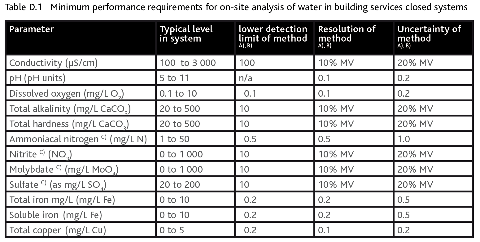
MV = measured value
A) Many test kits and field equipment can achieve better than the values in Table D.1. However, Table D.1 is considered the minimum acceptable performance.
B) Columns 3-5 all apply coincidentally for the performance criteria to match.
C) Where dilution is used to extend the range of the available test method then deionized water should be used.
(Reproduced with the permission of the author and publisher – British Standards Institution (BSI))
Author’s Recommended Field Test Methods for BS 8552:2012 – Table D.1:
When to use electronic test meters:
Conductivity (μS/cm)
Reagents required: Standard Conductivity Solution 1413 μS
A conductivity meter measures the amount of electrical resistance in a solution. Most commercially available conductivity meters (hand held or pocket) will support the above requested levels. When dealing with conductivity measurements there can sometimes be an issue when converting between conductivity (μS/cm) and TDS (mg/l) if required. Please note that Table D.1 only requires conductivity but if for any reason there is a need to convert an approximate conversion factor of 0.65 could be used (i.e. Cond x 0.65 = TDS). Conductivity measurements are easy to do and can be used as a quick ‘health check’ of your system when compared with the make-up water conductivity level.
pH (pH units)
Reagents required: pH 4, 7 & 10 Buffer Solutions
A pH meter measures the electrical potential difference between a pH electrode and a reference electrode and displays the result in terms of the pH value of the solution being tested. Most commercially available pH meters (hand held or pocket) will support the above requested levels. There are pH papers in various ranges readily available (i.e. 0-14 / 6-10 / 7-14) and many photometer models offer some limited pH ranges but neither format will provide the accuracy level required under Table D.1 (i.e. Resolution = 0.1 pH unit). It is important to note that photometer colourimetric readings are strongly subject to the buffering capacity and salt contents of your sample water and as such pH meters are best used.
Dissolved Oxygen (mg/l O2)
Reagents required: None
Dissolved oxygen meter are available in a number of different formats centring on how the oxygen-sensing probes function. The more common meters have probes that contain optical fluorescence sensors, galvanic sensors or polarographic sensors (no comments on the relative performance of the various methods is being offered in this article). Most commercially available dissolved oxygen meters (hand held or pocket) will support the above requested levels. There are dissolved oxygen methods available on many photometer models which typically involve vacuum vial (liquid reagent) technology. However photometer vacuum vial methods are usually for low level oxygen testing (typically < 1mg/l) and do not cover the required range in Table D.1. High range visual comparator methods using vacuum vials will support the range but unfortunately they do not support the required resolution of 0.1mg/l O2. Calibration of dissolved oxygen meters is typically based on an oxygen in-air calibration.
Generally the issues surrounding dissolved oxygen testing involves the correctset up of the sampling equipment. Experience will tell you that stabilisation ofthe sample line is an absolute necessity. This is done by flowing sample waterthrough the sample line for several minutes prior to sampling to ‘remove’trapped oxygen which otherwise would cause erroneous oxygen interferencewith your reading.
When to use titration methods:
Total (M) Alkalinity (mg/l CaCO3)
Reagents required: TA4 – Indicator, PA2/TA2 – HR Titrant or TA3 – LR Titrant
The recommended method for Total (M) Alkalinity determination involves a titration method using an indicator (TA4 – Indicator) and titrating with a dilute sulphuric acid titrant (PA2/TA2 – HR Titrant or TA3- LR Titrant) to a yellow/orange colour change endpoint. The endpoint equates to approximately pH = 4.5 at which point all types of alkalinity have been neutralised. As with most titration methods, the accuracy of the titration can be increased by varying the titrant strength and/or the sample size (see example tables below). Colourimetric methods for alkalinity determination are available on photometers and comparators but these methods do not offer consistency in the required resolution in Table D1 of BS8552:2012. Alkalinity methods on photometers and comparators are generally considered to be for the leisure market (i.e. swimming pools), where the water matrix is less diverse and the results less critical.
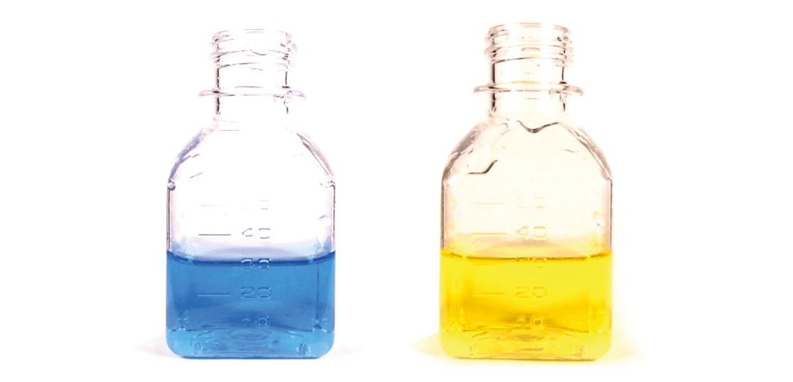
Figure 1 – Total (M) Alkalinity titration method – Sample colour with TA4 Indicator added: before and after titration.
Tables 2 & 3 – Total (M) Alkalinity titration method with different strengths of Sulphuric Acid Titrant and different Sample Size
Table 2:
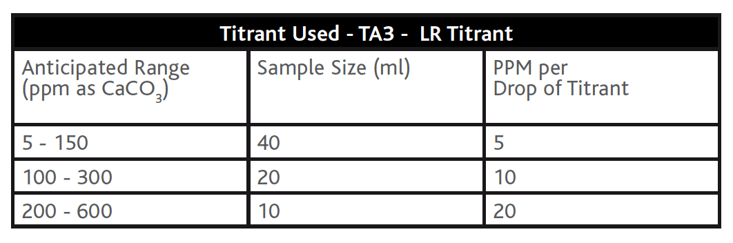
Table 3:

Total Hardness (mg/l CaCO3)
Reagents required: TH2 – Total Hardness Buffer, TH5 – Total Hardness Indicator, TH3 – LR Titrant, H/TH4/CH4 – HR Titrant
The recommended method for total hardness determination involves a titration method using a buffer (TH2 – Total Hardness Buffer), an indicator (TH5 – Total Hardness Indicator) and titrating with an EDTA titrant (TH3 – LR Titrant or H/ TH4/CH4 – HR Titrant) to a blue colour change end point. As with the Alkalinity titration methods above, the accuracy of the Total Hardness titration can be increased by varying the titrant strength and/or the sample size (see example tables below). Colourimetric methods for hardness determination are available on photometers and comparators but these methods do not offer consistency in the required resolution in Table D1 of BS8552:2012. Hardness methods on photometer and comparators (like alkalinity above) are generally considered to be for the leisure market, where the water matrix is less diverse and the result less critical.
Figure 2 – Total Hardness titration method – Sample colour with TH2 – Total Hardness Buffer & TH5 – Total Hardness Indicator added; before and after titration.

Tables 4 & 5 – Total Hardness titration methods with different strengths of EDTA Solution Titrant and different Sample Sizes.
Table 4:
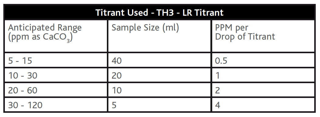
Table 5:

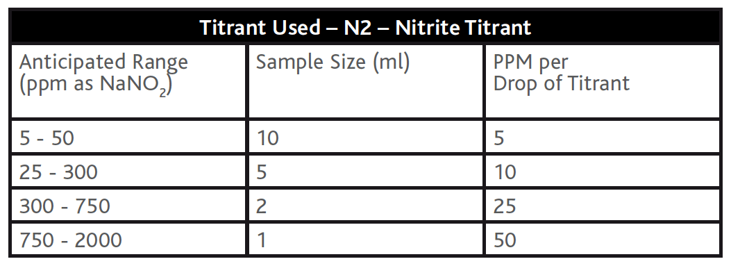
Nitrite (mg/l NO2)
Reagents required: N1 – Nitrite Indicator, N2 – Nitrite Titrant
Nitrite is one of the most common corrosion inhibitors used to treat closed water systems. The recommended method for testing Nitrite involves a titration method using an indicator (N1 – Nitrite Indicator) and titrating with a Cerium salt titrant (N2 – Nitrite Titrant) to a blue colour change end point. This test has no known interferences, however if you ‘miss’ the blue endpoint while titrating and continue to add the titrant the endpoint colour will migrate to green as you’re adding more of a ‘yellow’ coloured reagent to a previously ‘blue’ sample. The accuracy of the nitrite titration can be increased by varying the sample size (see example tables below). Colourimetric methods for nitrite determination are available on photometers and comparators but these methods do not offer consistency in the required resolution in Table D1 of BS8552:2012.
Figure 3 – Nitrite titration method – Sample colour with N1 Indicator added; before and after titration.
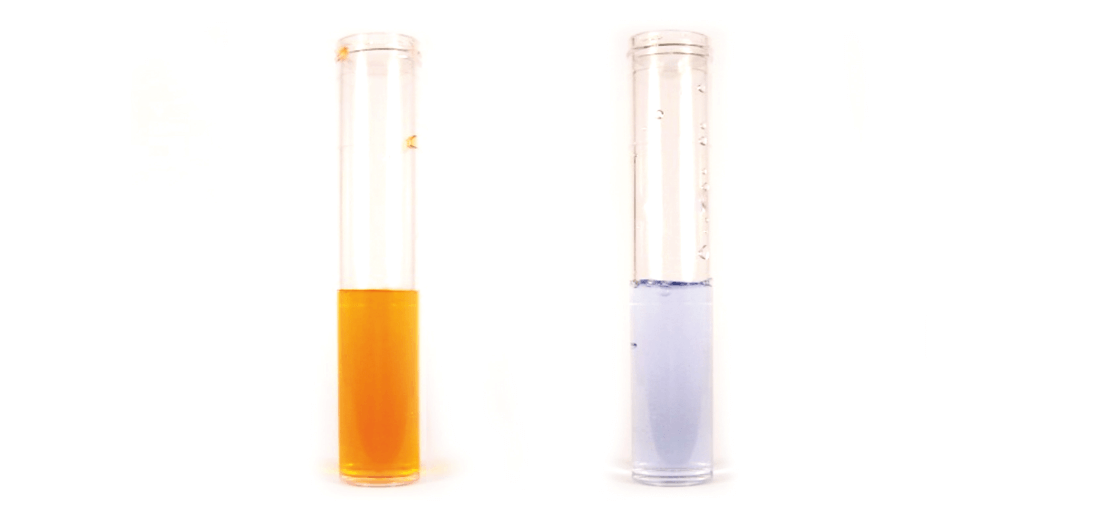
Table 6 – Nitrite titration methods with different Sample Sizes.
When to use colourimetric methods:
Ammonical Nitrogen (mg/l N)
Reagents required: Ammonia No. 1 Tablets, Ammonia No. 2 Tablets
The recommended method for testing ammonia involves a colourimetric method with a photometer based on salicylate chemistry using Ammonia No 1 tablets and Ammonia No 2 tablets to form a blue coloured complex that is proportional to the concentration of ammonia present. Note, the actual colour that develops will appear green due to the background ‘yellow’ colour of the indicator in the reagent added (see Figure 4 below). Strong alkali or acid sample waters need to be adjusted to approximately pH 7 prior to testing and any residual chlorine should be removed with a Thiosulphate solution as per the test method. Visual comparator ranges are available using the same reagents and colour development chemistry, however these comparator methods do not offer the required resolution in Table D1 of BS8552:2012.
Figure 4 – Colour of Ammonia tests on 10ml samples containing 0 – 1mg/l Ammonia

Molybdate (mg/l MoO4)
Reagent required: Molybdate HR Reagent
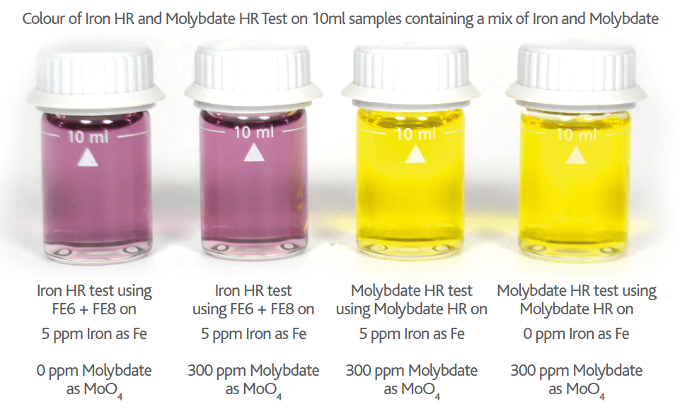
Molybdate is one of the most common corrosion inhibitors used in closed water systems and as such testing for Molybdate is included in Table D.1. The recommended method for testing molybdate involves a colourimetric method with a photometer based on thioglycolate chemistry using Molybdate HR Reagent (or FE6 Reagent) to form a yellow coloured complex which is proportional to the concentration of molybdate present (see Figure 5 below). It is important to note that the Molybdate HR Reagent and FE6 Reagent are both thioglycolate based reagents and are acidic & colourless in nature. With the addition of this acidic thioglycolate reagent to a closed water system that has Molybdate present, a yellow Thioglycolate-Molybdate complex is formed. Please note that the acidic nature of the thioglycolate reagent is sufficient to acidify a sample from a closed water system operating in the pH range 9 – 10, producing the yellow complex. If this sample was then adjusted back to alkali conditions with an alkaline reagent, the yellow colour would disappear even though the Thioglycolate-Molybdate complex would still be present. This change of complex colour based on the sample pH is the fact that allows thioglycolate to be used for testing BOTH Molybdate and Iron (to be discussed later) without one interfering with the other.
Equation 1
Molybdate sample + Thioglycolate Reagent (in acidic conditions) = Yellow complex
Equation 2
Molybdate sample + Thioglycolate Reagent (in alkali conditions) = Colourless complex
Visual comparator ranges are available using the same reagents and colour development chemistry, however these comparator methods do not offer the required resolution in Table D1 of BS8552:2012.
Please note if Nitrite is present in your Molybdate sample, the Nitrite will cause an orange colour interference proportional to the level of Nitrite present (see Figures 6 & 7 below). This Nitrite interference can be removed by adding a small amount (0.25g) of TN1 Reagent. TN1 is a sulphamic acid based reagent and removes the Nitrite interference by bubbling it off as nitrogen gas (see Figure 7 below).
Figure 5 – Colour of Molybdate HR Reagent tests on 10ml samples containing 0 – 300mg/l Molybdate (as MoO4)
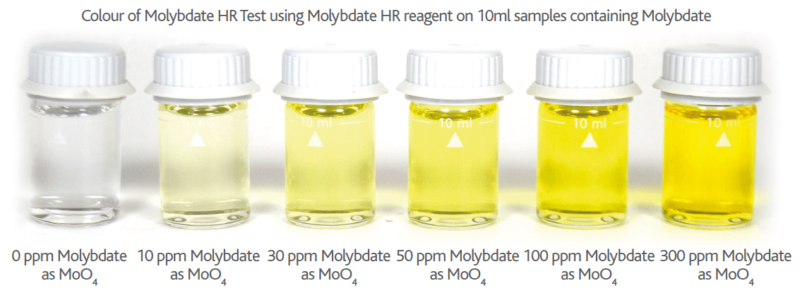
Figure 6 – Colour of Nitrite interference on Molybdate HR Reagent tests on 10ml samples containing 60mg/l Molybdate (as MoO4) with increasing levels of NaNO2 (0 – 200ppm)
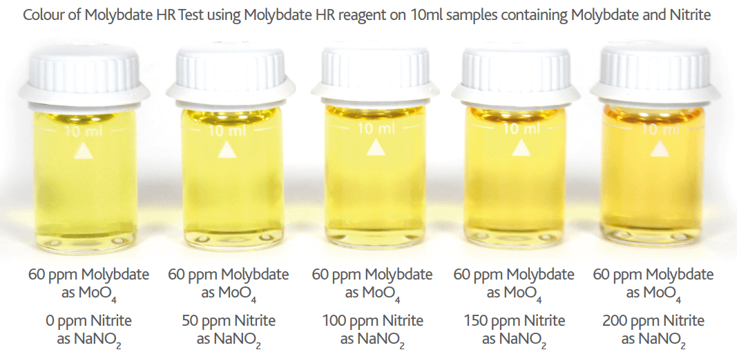
Figure 7 – Colour of Nitrite interference on Molybdate HR Reagent tests on 10ml samples containing 60mg/l Molybdate (as MoO4) with 1000ppm of NaNO2 (with & without TN1 Reagent)

Iron, Total & Soluble (mg/l Fe)
Reagents required: FE6 – Iron HR Reagent, FE8 – Iron HR Reagent
The recommended method for testing Iron (Total & Soluble) involves a colourimetric method with a photometer based on the same thioglycolate chemistry used for testing Molybdate (i.e. FE6 Reagent (or Molybdate HR Reagent)) to form an initial ‘colourless’ complex which is proportional to the concentration of iron present. At this stage, in the test method, it is understandable if you are unable to tell how intense the ‘colourless’ complex is! However, this initial reagent addition may result in a ‘yellow’ coloured complex, but this is not from iron. If a yellow complex develops after the addition of FE6 Reagent, it is the ‘interference’ showing from molybdate being present in your ‘iron’ sample. As with molybdate testing the iron-thioglycolate complex is coloured or colourless dependent on pH. The iron-thioglycolate complex is ‘colourless’ when acidic (molybdate complex is yellow) and ‘purple’ in alkali conditions (molybdate complex is colourless). This makes the coloured/colourless complexes directly ‘opposite’ for iron and molybdate which is why this chemistry can be used in the presence of both species without allowing interference to occur (see equations 3 & 4 for confirmation). To complete the iron test a second alkali reagent (FE8 Reagent) is added to take the iron sample to an alkali pH condition, sufficient to allow the iron-thioglycolate complex to change to purple in colour (see Figure 8 below). Note, if the FE8 reagent is not added the sample would remain colourless (or yellow) in acidic conditions regardless of the level of iron present.
Equation 3
Iron sample + Thioglycolate Reagent (FE6) + Alkali Reagent (FE8) (i.e. alkali conditions) = Purple complex
Equation 4
Iron sample + Thioglycolate Reagent (FE6 ONLY) (i.e. acidic conditions) = Colourless complex
Visual comparator ranges are available using the same reagents and colour development chemistry, however these comparator methods do not offer the required resolution in Table D1 of BS8552:2012.
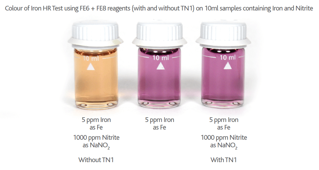
Please note if Nitrite is present in your Iron sample the Nitrite will cause an orange colour interference proportional to the level of Nitrite present (see Figures 9 & 10 below). This Nitrite interference can be removed by adding a small amount (0.25g) of TN1 Reagent. TN1 is a sulphamic acid based reagent and removes the Nitrite interference by bubbling it off as nitrogen gas (see Figure 10 below).
Figure 8 – Colour of Iron HR tests on 10ml samples containing 0 – 10mg/l Iron (as Fe)
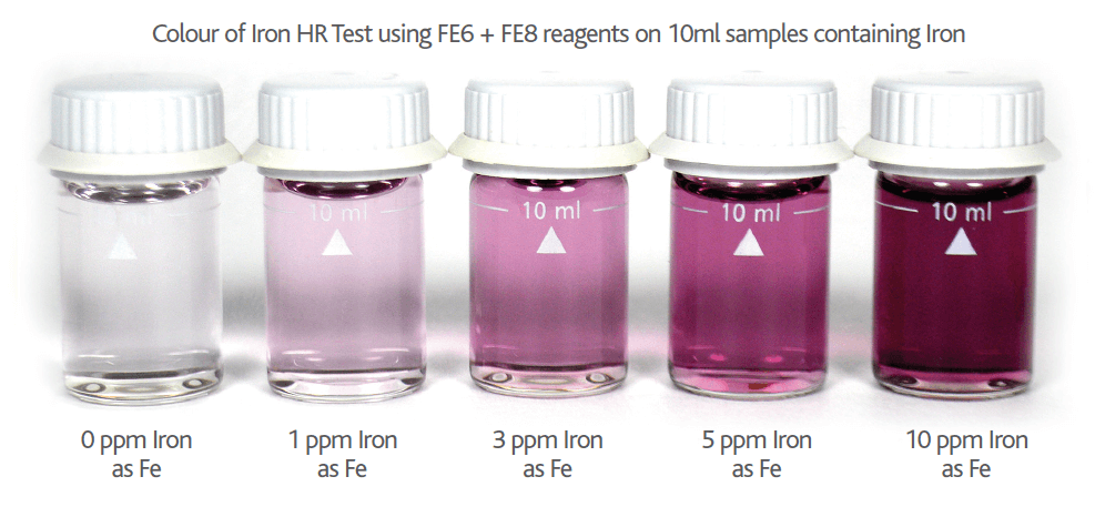
Figure 9 – Colour of Nitrite interference on Iron HR Reagent tests on 10ml samples containing 3mg/l Iron (as Fe) with increasing levels of NaNO2 (0 – 1000ppm)

Figure 10 – Colour of Nitrite interference on Molybdate HR Reagent tests on 10ml samples containing 5mg/l Iron (as Fe) with 1000ppm of NaNO2 (with & without TN1 Reagent)
Iron & Molybdate + Thioglycolate chemistries explained (FE6, FE8 & Molybdate HR Reagents)
Earlier we discussed the recommended colourimetric chemistry used for both Molybdate and Iron testing. We found it involves Thioglycolate chemistry (FE6 Reagent & Molybdate HR Reagent) for both of these key parameters, and that when the tests are performed ‘correctly’ (i.e. at the correct pH), there is no colour interference occurring.
This fact cannot be overstated as Molybdate is probably the most widely used corrosion inhibitor in closed water systems and the performance of a Molybdate inhibitor programme is commonly assessed by measuring the iron corrosion levels present. It is imperative to be able to test for either Molybdate (Molybdate HR Reagent) or Iron (FE6 & FE8 Reagents) in a water sample when both are present with NO interference occurring.
As noted previously, thioglycolate chemistry used for testing Iron (i.e. FE6) is the same chemistry used to test for Molybdate (i.e. Molybdate HR) but the two ‘complexes’ do not interfere with one another.
When thioglycolate is used in acidic conditions with Molybdate and Iron both present, a yellow colour will develop which is the thioglycolate-molybdate complex. Conversely when thioglycolate is added under alkali conditions to a solution with both Molybdate & Iron, the Thioglycolate-Iron complex forms which is ‘purple’ (see Figure 11 below).
So when the pH is controlled to acidic or alkali conditions you can accurately test for either molybdate or iron present and have NO interference occur.
Figure 11 – Colour of Iron HR test (acidic conditions) and Molybdate HR test (alkali conditions)
Copper, Total (mg/l Cu)
Reagents required: Copper No 1 Tablets, Copper No 2 Tablets
The recommended method for testing copper involves a colourimetric method with a photometer based on Bicinchoninate chemistry using Copper No 1 tablets and Copper No 2 tablets to form a purple coloured complex that is proportional to the concentration of copper present (see Figure 12 on next page). Visual comparator ranges are available using the same reagents and colour development chemistry for copper, however these comparator methods do not offer the required resolution in Table D1 of BS8552:2012.
Figure 12 – Colour of Copper test on 10ml samples containing 0 – 5mg/l Copper (as Cu)

When to use turbidity methods:
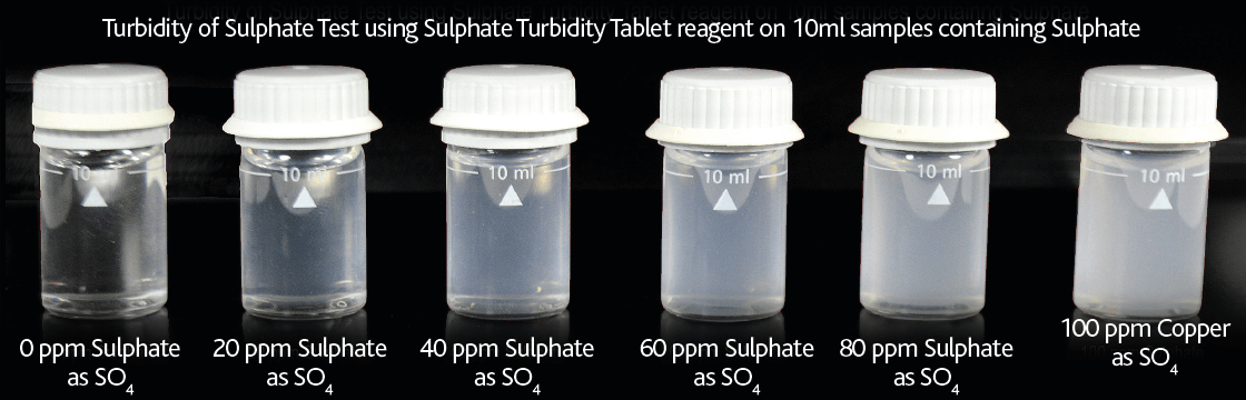
Sulphate (mg/l SO4)
Reagent required: Sulphate Turbidity Tablets
The recommended method involves using an electronic photometer and barium sulphate turbidity chemistry (Sulphate Turbidity Tablets) where the amount of turbidity generated is directly proportional to the concentration of sulphate present. Visual turbidity tube ranges are available using the same reagents and turbidity chemistry for sulphate, however these turbidity tube methods do not offer the required resolution in Table D1 of BS8552:2012.
Figure 13 – Clarity of Sulphate Turbidity test on 10ml samples containing 0 – 100mg/l Sulphate (as SO4)
Summary/Conclusions
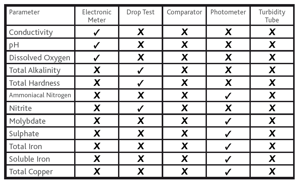
The above information overviews the ‘Author’s recommended field test methods’ for obtaining field test results that are consistent with the range, detection limit and resolution as prescribed in BS8552:2012 Table D.1. The following table summarises the recommended method type for each of the noted parameters.
Table 2
Summary of Method Type versus Parameter
Good Practice Techniques
The following are some good practice techniques that will help to minimise error and ensure your results are as accurate as the chosen test method allows.
1. Keep your sample equipment (syringes/vials/beakers/titration bottles) clean and free from build-up of residue from previous testing.
2. Always keep the dropper tips and caps clean. Replace caps immediately after use to reduce the possibility of cross-contamination of reagents. To minimise the possibility of contamination from sample water, do not touch the dropper tips to the sides of the titration bottles.
3. Always dispense ‘drops’ from the dropper bottles with the bottle held in a totally inverted orientation (i.e. not held at a 45 degree angle). Use only a minimum amount of pressure to allow the drop to form and fall without squeezing the dispensing bottle.
4. Always rinse your sample equipment (syringes/vials/beakers/titration bottles) with the water under investigation prior to proceeding with measuring out your required sample volume.
5. Always use the calibrated syringes provided to measure sample volumes. Remember to ‘read’ the volume from where the bottom of the liquid meniscus touches a calibration mark on the syringe. Remember to remove any trapped air from the syringe before moving the plunger to ‘dispensing’ volume position.
6. If your result is near to the measuring limit for any given test method, consider repeating the test with a 1:1 dilution (i.e. 5ml distilled water + 5ml sample water for your 10ml photometer sample). The repeated dilution result should be ‘half’ of the original result. If the diluted result is significantly different from half, repeat diluted result on a fresh sample.
7. If the sample water is ‘turbid’ you may require filtration through a GF/C filter paper. Always filter a larger volume than is needed for your test to guarantee you will have sufficient volume for your test. If using the ‘Leur Lock’ syringe filter system remember to keep the O-ring inside the filter in place when adding your filter paper. Failure to keep the O-ring in place will allow the filter to leak ‘unfiltered water’ during filtration step.
Permission to reproduce extracts from British Standards is granted by BSI Standards Limited (BSI). No other use of this material is permitted.