As featured in Waterline Winter 2022-23
How do I interpret my on-site test results?
Ian Penney, DTK Water
Industrial water treatment in one form or another has been around for a very long time. Without looking too hard I found a citing for phosphorus as a corrosion inhibitor used in the construction of the iron pillar of Delhi more than 1500 years ago 1. And if that’s not long enough ago, the ancient Greeks in the time of Hypocrates (400 BC) discovered the sanitizing power of copper. Apparently, they prescribed copper for pulmonary diseases and for purifying drinking water.
I think you would therefore agree that the use of chemical additives for the treatment/prevention of water borne and/or water formed issues like corrosion, scale and microbiological growth problems goes a long way back. What is not quite so well publicized is the level of testing and control that has been needed throughout the years to keep the chemicals and the water itself in check.
Those of us who have been in the industry for longer than we care to remember will quickly tell you about the ‘good old days’ when companies like Betz, Dearborn and Houseman provided weeks if not months of training for new recruits, and they’re also quick to tell you that ‘it doesn’t happen like that anymore’.
The following article is not the ‘be all and end all’ with respect to recommendations and interpretation of on-site testing/results and I am sure there will be discussions on areas that have been missed. It also needs to be noted that these are what the author considers to be the ‘minimum tests that are usually needed’, not the full suite of tests that can be done. However, hopefully it goes someway in helping those that are new into the water treatment industry to understand their results and what remedial actions one might take accordingly. In addition, any reference to usual, expected results or standard methods are drawn from the authors experience and may differ for the user, dependent on the standard operating procedure of their company.
See – How to Use a Test Kit? – Toolbox Talk March 2021
Raw/Make-Up Water (MU)
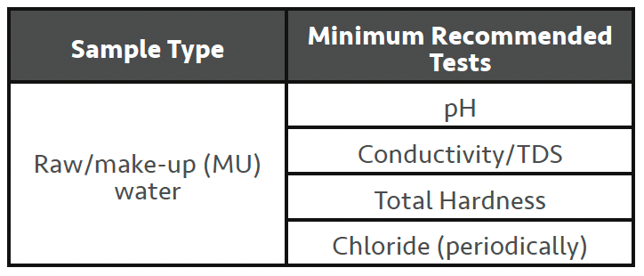
Raw/make-up water (MU) should be tested to at least a minimum level every time you visit site for a service visit (SV). A minimum level of tests is shown here. This is especially true with recent climate issues resulting in areas of drought and/or flooding which can affect the make-up quality of the system(s) being served (closed system/cooling tower/boiler).
• Conductivity – measures the dissolved solids level and can be used to quickly indicate if your site is experiencing a change in MU water quality when compared to previous readings.
• pH – again, confirms MU water quality (can indicate contamination, but the likelihood of mains water contamination is not very common).
• Hardness – confirms MU water quality and can be used to diagnose/set-up any pre-treatment plant that exists downstream. If the hardness level has increased, an on-site water softener’s regeneration frequency will likely need resetting. Failure to address can result in softener overruns and scale control issues.
• Chloride – chloride needs to be checked periodically and whenever a change in ‘normal’ MU water quality is suspected.
See – What is Conductivity? – Toolbox Talk Feb 2022 V3
Softened Water
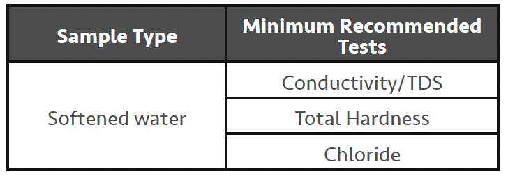
Since you’ve tested your MU water to the minimum level as above, you really need only check the performance of the water softening process. Conductivity/TDS has been included as it’s a simple test which can quickly indicate issues with water softener regenerations. As you may know a water softener requires regenerating with salt (sodium chloride) after it has been ‘exhausted’ by removing hardness from the inlet MU water.
• Hardness – A properly functioning water softener should be capable of providing < 2ppm hardness.
• Chloride (Conductivity/TDS) – This is to check if your water softener has regenerated properly and rinsed all the excess salt off the softener before going into service. To accurately assess this, you should test the softener immediately after it finishes the regeneration process, before it goes into service, which is not always easy to catch naturally. Chloride levels should be no greater than the MU water level. If safe to do so, performing a regeneration while you are on-site can allow this check to be made.
Overview of the softener regeneration process (4 steps):
1. Backwash – this step sends water in the reverse direction through the softener vessel to remove particulates that have been ‘filtered’ from the water flow by the softener resin. Backwash is usually performed at 1.5-2.0 times the forward service flow rate (for typically 10-15 mins).
2. Brine Draw – this step introduces salt on to the resin bed via a venturi system. Typically, a 10% salt (or 40% saturated salt solution) is used to regenerate a softener resin. Brine draw is run at normal service flow rate (for typically 20-30 mins).
3. Slow Rinse – this step continues to flow water (only) through the softener at normal service flow rate so the brine solution can be ‘moved’ through the entire resin bed (for typically 20-30mins).
4. Fast Rinse – this step increases the flow rate of water through the softener to 1.5-2.0 times normal service flow rate so the brine solution can be totally washed from the entire softener resin bed (for typically 10-15mins).
Water Softeners – Toolbox Talk May 2022 v2
Other forms of pre-treatment
There are many other forms of pretreatment available, de-alkalisation, reverse osmosis, de-mineralisation, ultra-filtration etc. Overall recommendation here would be to assess what the pre-treatment is designed to do and then like with the softener above, test that it has performed successfully. A quick example, a de-mineralisation plant can produce near distilled water quality with almost zero dissolved solids. So, a simple conductivity check would be a good measurement to assess performance. Remember, these are the minimum recommended tests.
Closed Water Systems
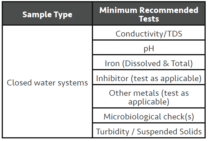
Closed water systems, as the name implies are closed to the greater environment and use very little MU water in their normal operation. A properly ‘tight’ system will have no more than 5% MU water annually. As such closed water systems do not concentrate up the amount of dissolved solid present in the MU water. This fact usually means ‘calcium’ based scale formation is not as significant a risk as corrosion is for these systems. Minimum recommended tests for a closed water system would include the following:
• Conductivity – the conductivity of a closed system can vary based on the initial MU water conductivity and the type of chemical treatments that are in use. Measuring the conductivity on start-up and on each SV allows you to monitor in-spec trends and identify any large changes in readings. A significantly lower conductivity reading may suggest a system leak has occurred with new MU water being added which dilutes the system, reducing the conductivity level from the last visit. A significantly higher reading may suggest that there has been an addition of a chemical(s) since the last visit, or some form of contamination has occurred. Dependent on the type of closed system (condenser, chilled, hot water) will determine what type of contaminant you should probably look for.
• pH – routine monitoring (trending) of the pH, like with conductivity will give a reasonable confirmation that the system is running OK. High pH could mean excess chemical addition or some form of contamination. Low pH would usually mean some form of contamination has occurred or a high level of sulphate reducing bacteria (SRB’s) may have taken hold in the system giving off low pH hydrogen sulphide as a byproduct. Systems with measurably high SRB’s will likely have a heavy biofilm formation as well.
See – What is Biofilm? – Toolbox Talks June 2020 v2
• Hardness – Not normally required. As closed systems do not ‘cycle-up’ from evaporation, hardness levels should stay around MU water levels or just below as some hardness may have dropped out of solution.
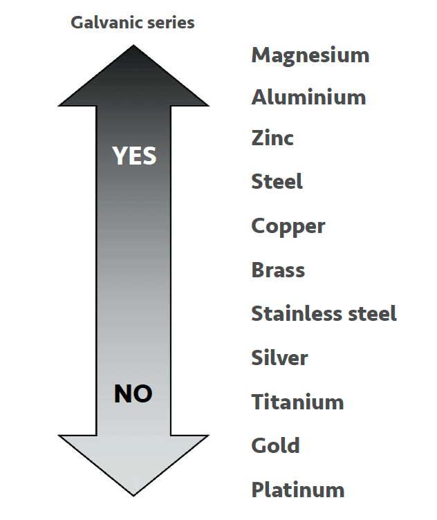
• Iron – Unlike hardness, corrosion is a common problem and is typically the main cause of failures with closed water systems. Corrosion problems can sometimes link right back to the installation of the system, and all too often are the result of an insufficient pre-commissioning program. See the galvanic series for metals in Figure 1 below. Both dissolved and total Iron should be tested on each SV.
Figure 1
• Dissolved iron – To properly assess dissolved iron, filter your sample through a 0.45-micron filter paper, then proceed with your test. The level of dissolved iron can usually be used as a measure of active corrosion of the system.
• Total Iron – For total iron, do not filter your sample but instead perform an acid digestion step on the unfiltered sample for a few minutes prior to adding your colour developing reagent; this will give you a total iron result.
• Suspended Iron – When you have both dissolved and total iron results, subtract the dissolved from the total to obtain your suspended iron level. Unfortunately, it’s not always easy to assess the significance of a suspended iron result. It can be historic corrosion, but high levels of suspended iron would normally suggest a need for side-stream filtration (see Figure 2) to work on reducing suspended material levels.
• Installing a corrosion coupon rack is always a good recommendation. It will allow you to assess levels of corrosion across the various materials of construction (mild steel, copper, aluminum etc.) and give you a visual assessment of how your system is operating. FYI, a mild steel corrosion rate of less than 2 mils per year is considered an excellent result. It’s important to note that coupons should be installed for no less than 1 month and more normally coupons are installed for 3 months. There will be an initial high rate of corrosion that will occur when you first install your coupon(s), and this rate of corrosion will then tend to steady state. Assessing corrosion rates after a very short install periods will give skewed results due to the initial corrosion rate.
Note: Other metals involved in the system construction can be assessed in a similar way to iron levels as above, and corrosion coupons in most metal types are available for assessing on-site corrosion rates.
See – What is Corrosion? – Toolbox Talk Jan 2021
See – What are Corrosion Coupons? – Toolbox Talk June 2021
• Inhibitor Levels – One of the more important tests that should be performed each SV is a check on the inhibitor level. This article will not try and overview all the various inhibitor treatment programs or programs like VDI 2035 where chemical additives play a very small part in the overall control of the water treatment. In general, most closed water systems tend to be treated with molybdate-based or nitrite-based corrosion inhibitors as the primary chemical component. There are many proprietary blended inhibitors on the market in the UK today and selection of a suitable inhibitor is based on several factors like the materials of construction of the system, system temperature. As an example, a system using a primarily nitrite-based inhibitor program will result in a pH in the operating system of typically 9.5-10.5 and as such should not be selected for systems that have significant aluminium components. Proprietary blended products will likely also contain dispersants, yellow metal inhibitors and may have some form of hardness control.
Whichever inhibitor is in use, there should be clear guidance on the control levels needed and it should be tested for its active ingredient every SV. The test results are then used to assess whether any chemical additions need to be made to the operating system.
Note: Other tests that can be done on closed systems include alkalinities (P & M), chloride, hardness etc. but the above water tests should be sufficient to allow an operator enough information to keep control of any closed water system.
• Microbiological testing – There are several microbiological tests that can be done during a SV on a closed water system. These include dipslides for general bacteria levels (TVC’s), more specific dipslides for pseudomonas (aeruginosa or species) as well as tests for nitrite reducing bacteria (NRB’s) and sulphate reducing bacteria (SRB’s). For systems that contain glycol for freeze point depression, checks for yeast and moulds is a good recommendation. Any of these micro checks will require incubating your sample for prescribed times at set temperatures but will usually provide activity levels well ahead of samples sent to a laboratory.
See – What are Biocides? – Toolbox Talks Feb 2020
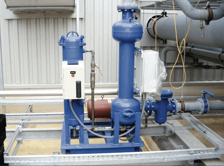
• Turbidity / Suspended Solids – A visual check of the water clarity is the easiest of tests but is always a good indicator of the state of the operating system. Turbidity / suspended solids is usually left as the visual check and an ‘appearance’ result is entered. If a multi-parameter photometer is used for site testing it’s likely that one or both tests can be performed by the electronic meter. High levels of turbidity / suspended solids should signal the need for some form of side-stream filtration to clean-up the circulating material which will reduce the potential for blockages and under-deposit corrosion should the material be allowed to settle out. An example of one type of side-stream filtration is shown in Figure 2 below. In this type of side-stream filter the water is sent in a vortex/cyclone motion through the filter and solids are thrown out of the water flow for collection and removal by purging.
Figure 2 – Centrifugal (Cyclone) Separator
See – What is Filtration? – Toolbox Talk Feb 2020
Cooling Tower Systems
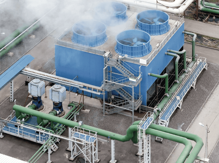
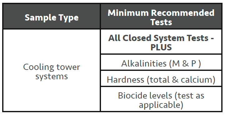
This article assumes the reader has a general understanding of how evaporative cooling tower systems function and will not try and cover the myriad of different types of evaporative cooling towers/systems. However, it is important to understand the ‘meaning’ of the word evaporative in the name, as this explains how cooling tower systems differ from closed water systems in one very important aspect. ‘Cooling’ towers are used to expel heat from some process needing to be cooled (i.e., machine cooling/air conditioning/refrigeration) via a water re-circulation system that eventually flows over a cooling tower. When operating, a cooling tower by design is open to the environment and will incur evaporation losses to varying degrees. It’s this evaporation loss that results in the concentrating up of the MU water dissolved solids level in the system. Commonly known as ‘cycling-up’, this aspect of cooling towers tends to change the emphasis from corrosion to scale formation when looking at the major concerns with using water as a heat rejection medium, unless some form of water softening is involved. In very general terms ‘all’ of the tests that have been discussed with closed water systems are applicable when routinely testing cooling towers. However, there is significant interest in the alkalinities (M & P) and the hardness levels (particularly calcium hardness) as they relate to the likelihood of scale formation. In most instances a measure of the water systems Langelier Saturation Index (LSI) 2 will be performed on the MU water and theoretical ‘cycles’ of this water to see how many cycles of concentration you can safely run to, based on the expected performance of the scale/corrosion inhibitor in use. Many modern inhibitors will allow a concentration of dissolved solids in the recirculating water up to a level which results in an LSI < +3.0-3.5.
See – What is Concentration Factor? – Toolbox Talk Feb 2022 v3
Figure 3
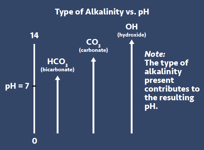
• Alkalinities (M, P & OH) – There are generally 3 types of alkalinities that need to be discussed when talking about general water chemistry, these are bicarbonate (HCO3) alkalinity, carbonate (CO3) alkalinity and hydroxide (OH) alkalinity (see Figure 3). If we look in very general terms at the characteristics of these alkalinity types, we can see that they have varying levels of alkaline nature
– HCO3 Alkalinity – exists to a maximum pH of approx. 8.0
– CO3 Alkalinity – exists to a maximum pH of approx. 10.5
– OH Alkalinity – exists to a maximum pH of approx. 14.0
All raw waters in the UK as well as elsewhere in the world have varying levels of HCO3 alkalinity (i.e., London has around 240ppm while areas around Glasgow has around only 20ppm). As this form of alkalinity can only produce a pH of around 8.0 and most importantly has a high solubility level in the presence of water hardness, it would seem to be ‘safe’ to use water with HCO3 alkalinity for most cooling water applications. However, it’s well-documented that when water with HCO3 alkalinity is heated, it will convert through chemical process to form CO3 alkalinity which has a higher characteristic pH of around 10.5. And if we continue to heat this water and apply pressure, like in a steam boiler application, the CO3 will react further generating OH alkalinity with a resulting increase in pH. We’ll look at OH alkalinity and its pH capability to pH of 14 later in this article when we talk about understanding boiler water testing. So, keep this concept in mind as we next look at water hardness …. the more you use water for heat rejection which will naturally increase the water’s temperature, the more CO3 alkalinity we will generate with a corresponding increase in pH.
• Hardness (Total & Calcium) – Testing the hardness levels each SV is key to monitoring the system for potential scaling issues. Monitoring the calcium hardness levels in the MU water and comparing it to the level of calcium hardness in the cycled-up cooling tower is referred to as performing a ‘calcium balance’. If MU water calcium hardness is 200ppm, and you were controlling your cooling tower at 3.0 cycles of concentration (CoC) then you would like to see a calcium hardness level of 600ppm in the cooling tower. Anything less than a factor of 3 would suggest some calcium is dropping out as scale formation. When we discussed alkalinities, it was mentioned that the more you heat water the more carbonate alkalinity is formed. Now is probably a good time to let you know that unlike most species that you can dissolved in water, the more heat the more you can dissolve i.e., sugar, salt etc., calcium carbonate (CaCO3) has an ‘inverse solubility’. This means that the higher the temperature, the more CaCO3 will drop out of solution. So, let’s be perfectly clear on this majorly important point …. We want to use water as a heat rejection medium; the more we heat the water the more CO3 alkalinity will form and the more heat we pick up, the more CaCO3 wants to drop out of solution. I think this could be referred to as a ‘perfect storm’ for the potential for hardness deposition. It’s for this reason that many systems will use partially softened MU water to reduce the risk of scale formation. It should be noted the author does not recommend using fully softened water as it reduces the natural buffering capacity of the MU water and makes it more corrosive in nature. Remember, scale formation can be reversed but corrosion is irreversible!
See – What is Scale? – Toolbox Talk Feb 2020
• Conductivity/TDS – Measuring conductivity/TDS has been mentioned under closed water systems but it’s important to note that it is usually used as a controlling parameter for cooling towers systems. An automatic bleed control system based on an in-line conductivity probe will control a bleed valve to maintain the required CoC.
• Biocides – Control of the microbiological content in a cooling tower system is critical for several reasons. We’ve all heard of the need to control Legionella bacteria to reduce the risk of someone contracting Legionnaires’ Disease as well as the need to control other pathogenic microbes. Control usually involves a combination of physical control of the cooling tower to reduce the risk of exposure to an aerosol during operation (i.e., drift eliminators), with the use of chemical and/or non-chemical biocides. It should be noted that microbiological control will also help to minimize the formation of biofilms which will reduce the possibility of blockages, low flow areas, poor heat exchange and lessen the possibility of under-deposit corrosion. Oxidizing biocides such as bromine, chlorine and chlorine dioxide are typically used on a continuous low level dosing program with evaporative cooling systems. These oxidizing biocides are routinely backed up with the use of a non-oxidizing ‘shock dosed’ biocide. Oxidizing biocides should be checked for the active level in the re-circulating water every SV.
Non-oxidizing biocides are usually dosed based on the system volume, but some types can be tested for. If an oxidizing biocide is in use you are required under HSG274 Part 1 3 to perform a weekly level check, record your results and take remedial actions if found to be out of specification. It’s important to not overdose the oxidizing biocide as it can promote higher corrosion levels.
• Dipslides – As with the oxidizing biocide, the current UK guidance in HSG274 Part 13 requires a dipslide to be performed every week to assess the general bacteria level that exists in the re-circulating cooling tower system. There are several different types of dipslides on the market. The different types refer to various ‘combinations’ of agar growth medium on each side of the dipslide paddle. The guidance requires at least one side of the dipslide to have TTC agar which will test for general aerobic bacteria levels.
See – What are Dipslides? – Toolbox Talk May 2020
Steam Boilers
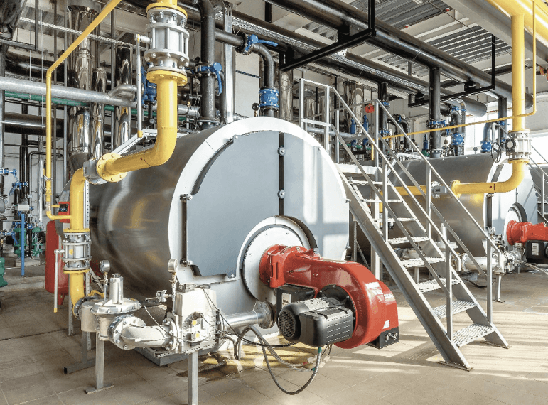
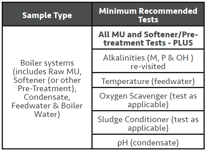
As with the preceding section on cooling tower systems, this article assumes the reader has a general understanding of how steam boiler systems function and will not try and cover the various equipment layouts and different boiler types that can exist with steam boiler systems. Current UK regulations/ guidance on operating steam boiler systems can be found in BS2486:19975. In very general terms we expect the following sequence of water qualities will need water testing to maintain satisfactory operating conditions.
– Raw MU water
– Softened MU water (requires ZERO hardness levels)
– Condensate returns
– Feedwater (combination of above waters in varying quantities)
– Boiler water
See – How To Take a Boiler Sample – Toolbox Talk July 2021 V2
• Alkalinity – Due to the temperatures and pressures involved within an ‘operating’ steam boiler, the alkalinity discussion which started with cooling tower systems now carries on and OH hydroxide alkalinity is formed in the boiler. Some might think this would be a problem due to the high expected pH but mild steel ‘prefers’ pH to be in the region of 11.0-12.5 which minimises the corrosion potential for the steel construction. Each boiler type (manufacturer) will have recommended levels for M & P alkalinity control which will provide suitable levels of OH alkalinity. Remember the formula for calculating your level of OH alkalinity (2P – M = OH). It’s this OH alkalinity when combined with the proper levels of your sludge conditioner additive (typically phosphate) that will allow any calcium or magnesium hardness to be properly ‘conditioned’ as a fluid sludge that can be removed via bottom blowdowns. It’s good to point out that where manual or automated surface blowdowns are employed, this will help to control the conductivity/TDS of the boiler water. If no surface blowdown is employed, the bottom blowdowns need to control both the conductivity/ TDS as well as sludge removal. It’s also important to note that allowing alkalinity levels to run too high in a boiler increases the surface tension of the water making it difficult for steam bubbles to break free at the water/steam interface and join the steam space in the boiler. This is referred to as ‘wet’ steam and results in carryover of boiler water into the steam which can cause problems related to steam use and steam trap operation.
• Temperature – We know levels of dissolved gases (particularly O2 & CO2) in water are directly proportional to the temperature of the water. As we do not want either dissolved gas to enter the boiler, both can cause corrosion problems, we try to maintain as high a feedwater temperature as possible. Condensate returns, live steam injection system and/or deaerators can be beneficial in raising the feedwater temperature. Usually the physical head pressure at the inlet to the feedwater pumps will be the limiting factor on how high a feedwater temperature you can operate at. Too high a feedwater temperature without sufficient head pressure will allow steam to form in the lowpressure inlet side of the pump, commonly referred to as steam cavitation.
• Oxygen Scavengers – As per above discussion on temperature, we don’t want any oxygen in our boiler feedwater. As such it’s common to dose an oxygen scavenger into the feedwater tank (or hot well) or directly into the feedwater line ahead of the feedwater pump. It’s important that the chemical addition is made with sufficient reaction time to scavenge all the oxygen before it reaches the boiler. Most sulfite-based oxygen scavengers are catalysed so the pick-up of oxygen is 10 to 100 faster than un-catalysed sulphite. When cobalt is used as the catalyst it will become inactive at a pH of 9.3 or greater, as such it’s important to use a separate mix/dosing tank just for the catalysed sulfite solutions. The cobalt catalyst precipitates as a brown floc, if you see this material collecting in the dosing tank, your catalyst has dropped out. When testing your sampled boiler water it’s important to test the sulphite level first as the level can change as your sample picks up atmospheric oxygen when cooling down. Other forms of oxygen scavenger include the below chemicals. Tannin is listed here but acts as both a filming agent (tannate film)4, as well as an oxygen scavenger.
– Sodium Sulfite
– Erythorbate
– Diethylhydroxylamine (DEHA)
– Hydroquinone
– Hydrazine
– Carbohydrazide
– Methyl Ethyl Ketoxime (MEKO)
– Tannin
It’s important to note that guidance for the control levels of each of these different types of oxygen scavengers is available from the boiler manufacturers or the chemical suppliers. If we take sodium sulfite as an example, you’re typically recommended a control level of 30-70ppm reserve be maintained (packaged shell & tube boiler up to 300psig operating pressure). However the author has found through experience that this control level works well for a boiler operated 24/7 but not when the boiler shuts down overnight and/or on weekends. When dealing with an intermittent use boiler it’s normally good practice to increase the reserve level to account for offline periods where some additional oxygen ingress may occur. For 9-5 only operation consider 50-100ppm reserves and for lower use boilers, consider 100- 150ppm reserves of sodium sulfite.
• Sludge Conditioners – As with oxygen scavengers there are many different formats for sludge conditioner with likely hundreds of proprietary blends. Some will attempt to keep solids in solution, to be removed with surface blowdown e.g., chelant based conditioners. Others like phosphatebased conditioners will seek to form ‘fluid’ sludges for bottom blowdown removal. Unlike oxygen scavenger dosing, if the boiler is ‘offline’ there is no real need to increase the reserve level as without actual feedwater entering the boiler, there is no increase in demand for the sludge conditioner. It’s important to note that the boiler sample needs to be filtered prior to testing for a phosphate reserve so it removed calcium/phosphate complexes that could test as reserve phosphate.
• pH (condensate) – We’ve discussed the breakdown of HCO3 to CO3 and finally to OH alkalinity but what wasn’t mentioned is that in these conversion reactions, CO2 is released which as a gas will travel off with the steam. If when the steam cools enough to condense to condensate, the CO2 dissolved back in as HCO3 we would be very happy with pH’s around the 8.0 level. However, unfortunately when the CO2 dissolves back into the condensate it forms carbonic acid H2CO3 which can lower the condensate pH to levels as low as 4.0-5.0 pH. This low pH condensate can corrode the condensate return pipework especially at the bottom of the pipe exposed to the acidic liquid. Many years ago I heard of a steam boiler account that ‘rotated’ their condensate pipework by 90 degrees every 2 years to extend the life of the pipework due to corrosion from 3 years to closer to 10 years.
Conclusion
Well, it seems I’ve run out of my allotted 5,000-word count.
Hopefully this article will be useful to those starting out in the field of water testing and can be used as the nucleus for future learning.
References:
1 – https://en.wikipedia.org/wiki/Iron_pillar_of_Delhi
2 – https://blog.orendatech.com/langelier-saturation-index
3 – https://www.hse.gov.uk/pubns/books/hsg274.htm
4 – https://feedwater.co.uk/sulphite-vs-tannin-oxygenscavenger-treatments
5 – BS 2486:1997 Recommendations for treatment of water forsteam boilers and water heaters – European Standards (en-standard.eu)