As featured in Waterline Winter 2025-26
Nostalgia isn’t what it used to be
D Prosser, a consultant for Treatment 4 Water
Over the many years practicing Cooling Water Technology there have been many changes. We have seen the demise (and almost extinction) of the hyperbolic natural draft, low maintenance cooling tower in favour initially of the various forced and induced draft lumber construction wood fill towers leading to the current non-lumber systems with plastic tower fill.
We have also seen regulation introduced to the evaporative cooling operations, both on the allowable chemicals to be used to control potential scale, corrosion and biofouling within the system and the requirement to prevent growth and transmission of possible pathogens that may be present in the cooling water following the outbreak of Legionnaires’ disease at the Bellevue-Stratford Hotel Philadelphia in 1976.
Direct cooling has been replaced with primary-secondary cooling using an intermediate heat transfer exchanger. Shell and tube condensers are widely used in power generation industry, chilled water for data centre cooling and major petrochemical processing. The more efficient plate and frame exchangers are found in all areas of cooling water – particularly in the food industry. Spiral heat exchangers are far less common despite the improved heat transfer and low fouling, being mainly found in oil refining.
We must question whether these developments are fully understood and considered to be an actual real benefit to cooling water technology and operation.
Education and training methods should also be questioned. Is “On the job with Molly” and the industry fixation with case histories a barrier to innovation and application of basic principles of engineering and chemistry?
This simple review leads to the question –
Is current water treatment practice in a HENRY FORD syndrome?

The cooling system can be split into three areas:
1. Heat pickup
a. Shell and tube
b. Plate and Frame
c. Spiral
2. Heat Rejection
a. Natural draft
b. Forced draft
c. Induced draft
d. Evaporative condenser
3. Heat transfer medium
a. Town mains
b. River water
c. Borehole
d. Sea water
e. Side stream options
Heat Pickup
For this discussion, we will only be reviewing primary-secondary cooling processes or process cooling involving a defined heat exchanger.
Shell and tube exchangers
1. Condensers
These are widely used in power generation to maximise the turbine efficiency by condensing the steam from the final stage, producing a small negative pressure. The tubes are mainly condensing steam rather than cooling condensate. The design follows the principle that the least fouling fluid is always in the shell side which facilitates the physical cleaning of possible foulants in the tubes.
More modern design utilises tubes with an expanded surface.
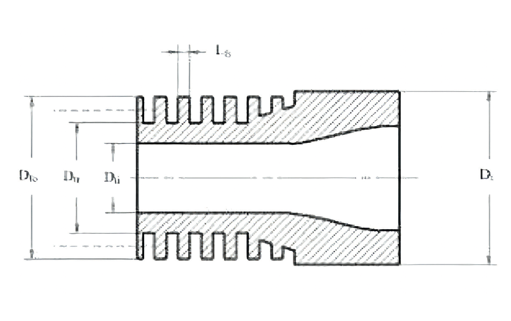
Typical surface area improvements by using integral low finned tubes are:
19.05mm OD with 8 fins / cm: 270%
25.4mm OD with 10 fins / cm: 330%
Depending on the fluids within the heat exchanger, the thermal performance improvement can range from between 20% to more than 100%, leading to an increase in the ∂T of the cooling water.
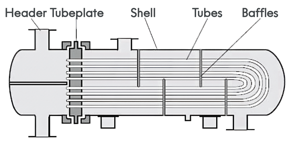
2. U-Tube exchanger
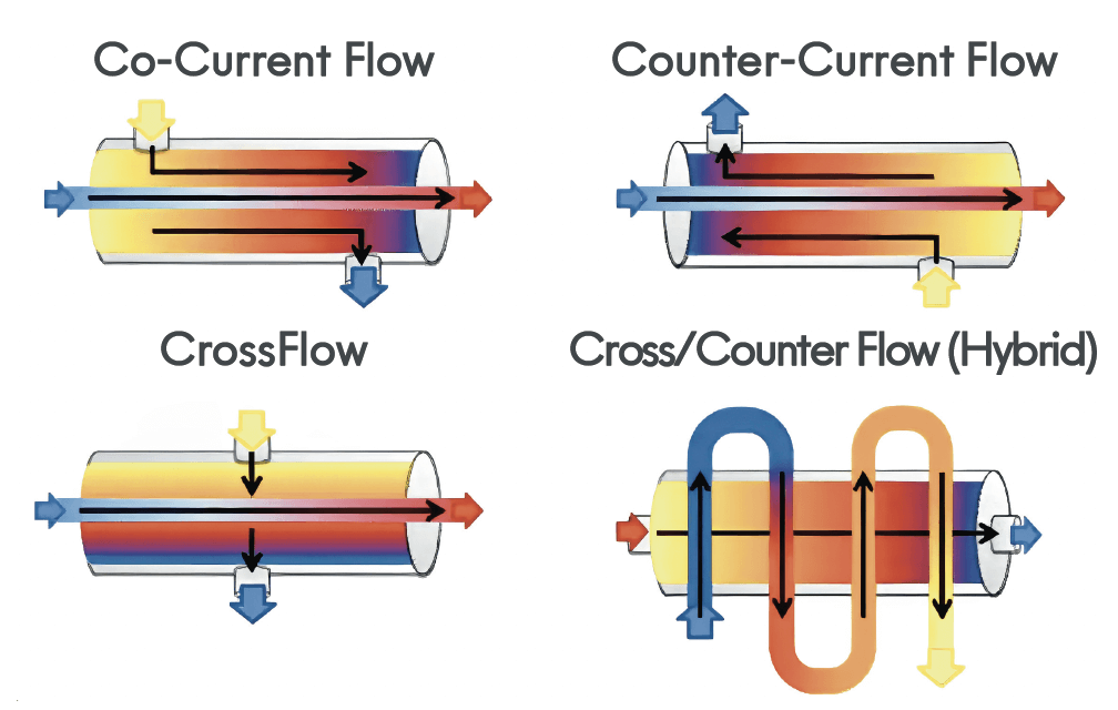
U-Tube exchangers are still quite common although not particularly efficient. In this case, the fluid most likely to foul is on the shell side as the tube bundle is generally removable to facilitate cleaning. The heat transfer is quite low because the water flow on the shell side is both co-current and counter current.
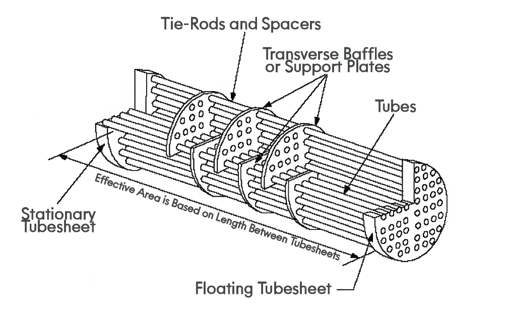
3. Floating Head Exchanger
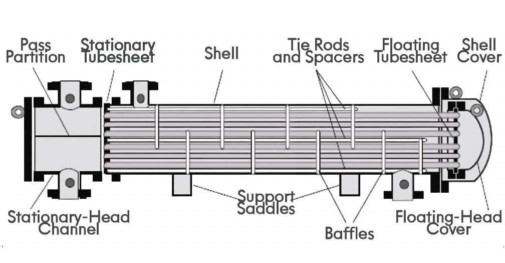
The floating head exchanger is an improvement on the simple u-tube as both sides of the tubes can be mechanically cleaned as the tube bundle can be removed. Also, the tube side configuration can be multi-pass, improving heat pickup. It also has the same shell side constraints as the u-tube. The tube bundle is usually baffled.
The baffles increase the velocity and turbulence over the tube enhancing heat transfer.
4. Plate and Frame Exchanger
The plate and frame exchanger is a versatile, highly efficient heat exchanger found in most areas of cooling water applications. The unit utilises thin corrugated plates in a rigid frame.
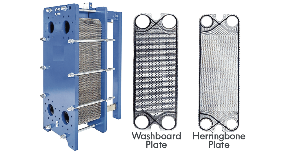
The plates are gasketed to prevent cross flow between hot and cold fluid. The fluid flows through a very narrow gap between adjacent plate and the design of the plate results in high turbulence at low flow rates resulting in heat transfer coefficients much higher than shell and tube exchangers. Hot fluid and coolant flow through alternate pairs of plates.
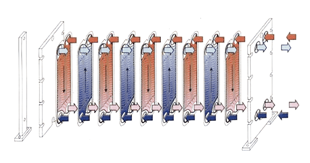
The exchanger has true counter current flow – maximising efficiency. The hot fluid is normally fed to the upper inlet with the coolant at the bottom.
When considering potential fouling fluids, the preferred configuration would be bottom entry as the velocity in the inlet channel decreases along the length of the exchanger since the inlet channel diameter does not change resulting in a tendency for suspended solids to deposit and block the inlet to the plate channel.
The plate and frame exchanger has a smaller footprint and is easier to maintain than shell exchangers since the unit can be opened and plates cleaned or replaced.
Plates can be produced in a variety of metals and alloys.
5. Spiral Heat Exchanger
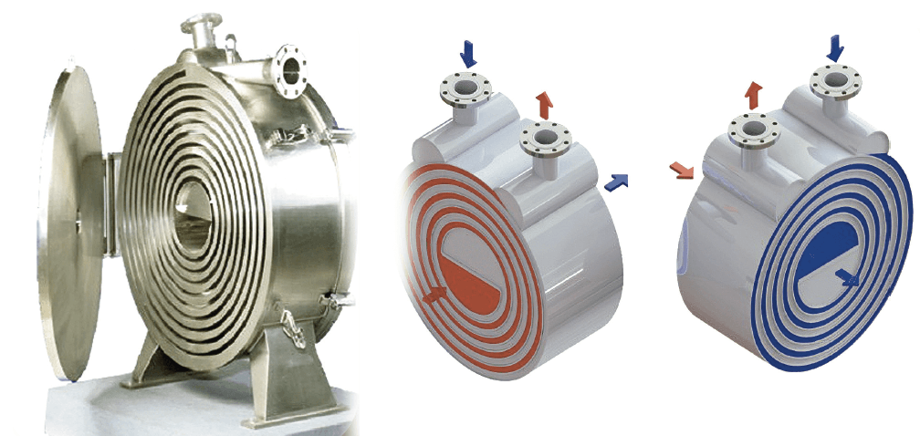
Generally found in refineries and petrochemical facilities.
They are true counter flow exchangers and are designed to be low fouling (self-cleaning). The fluids flow through a narrow spiral channel and the continuous change of direction creates high turbulence resulting in high heat transfer coefficients and low deposition potential.
These developments over the years have increased the heat acquisition (∂T on the cooling medium). This could be interpreted as an increase in the work done by the cooling medium.
Heat Rejection
1. Evaporative cooling
a. The principle of evaporative cooling was known by the ancient Egyptians as depicted in Fresco’s from 2500bc showing slaves fanning porous jars of water to cool rooms, but it was much later before an understanding of the physics was developed.

b. 16th Century – First Hygrometer
Leonardo da Vinci is credited with the invention of the first hygrometer using a ball of cotton wool to provide an indication of humidity. He is also credited with the first mechanical air cooler.
The device comprised a hollow wooden water wheel with a duct to a room. The air was cooled by the evaporation of the water from the stream. As the hollow wheel became submerged, the water entering the hollow section would compress the air forcing it down the duct.
c. 17th Century theorists – Pascal’s Rule
for Liquid Pressure
Blaise Pascal: Liquid pressure principle:
Pressure exerted anywhere on a confined liquid is transmitted unchanged to every portion of the interior and to all the walls of the containing vessel, and is always exerted at right angles to the walls. Robert Boyle:
If the temperature of dry gas is constant, then its volume varies inversely with the pressure exerted on it.
d. 18th Century – Fluid Dynamics
Bernoulli, Euler, Pitot, applied the techniques of mathematical physics to develop the science of fluid mechanics.
John Dalton – established the nature of evaporation, and its importance to the global cycle.
e. 19th Century – Darcy (1856)
established an understanding and quantitative characterisation of flow through porous media.
f. 20th Century – Willis Carrie
Development of a psychrometric chart like charts in use today along with the development of a formula that linked the transformation of sensible heat into latent heat during the adiabatic (no external heat input or output) saturation of air.
2. Natural Draft Towers
At the beginning of 20th century, water availability for industry was already of concern and recirculating cooling systems were being introduced using either an induced or forced draft fan. A design by Barnard in 1902 demonstrates a natural draft tower. The sides were open, and the water sprayed at the top over a fill of metal mesh.
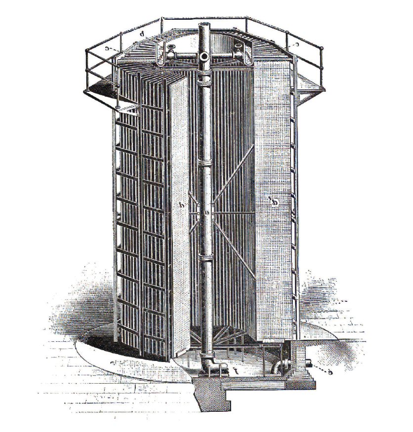
In 1916, Frederick van Iterson and Gerard Kuypers patented their work on the hyperboloid natural draft cooling process and the first build in the Netherlands in 1918 was followed by a tower at Lister Drive power station in Liverpool.
This design is considered the standard for natural draft towers because of their structural strength and economy of construction materials. The Hyperboloid shape enhances the convective air flow in the tower.

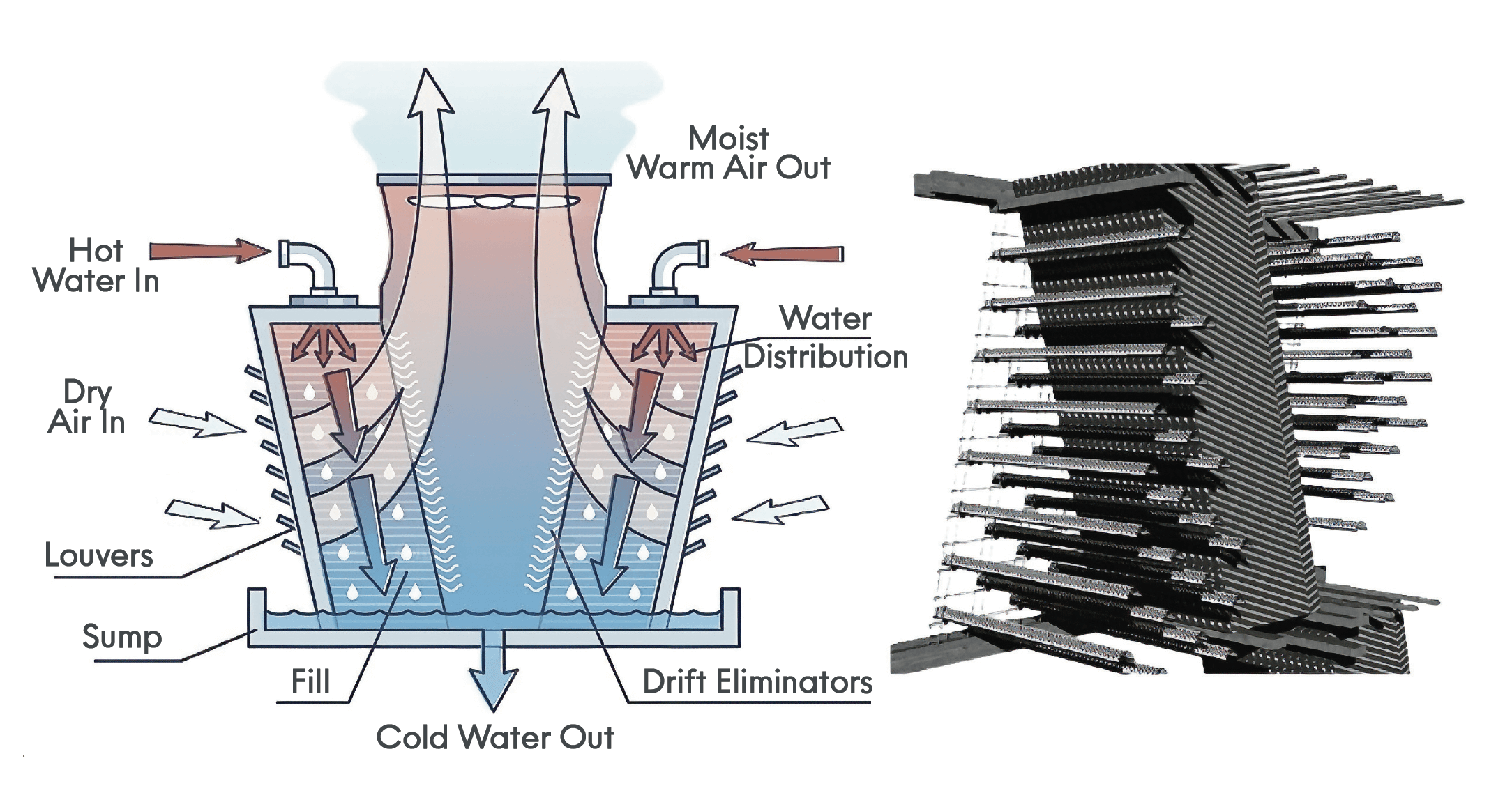
Hot water is fed to the lower third of the hyperboloid tower below a trapezoidal drift eliminator to remove entrained water droplets from the water vapour. The hot water is distributed usually with a spray system into the tower packing where it meets the cool natural draft and is cooled by differential evaporation. The early towers utilised a wood fill. Following the review of Legionellosis, wood has been removed from cooling systems as a potential substrate for biofouling.
With the decline in coal-fuelled power generation and Nimby we are seeing the demise (almost to extinction) of these icons.
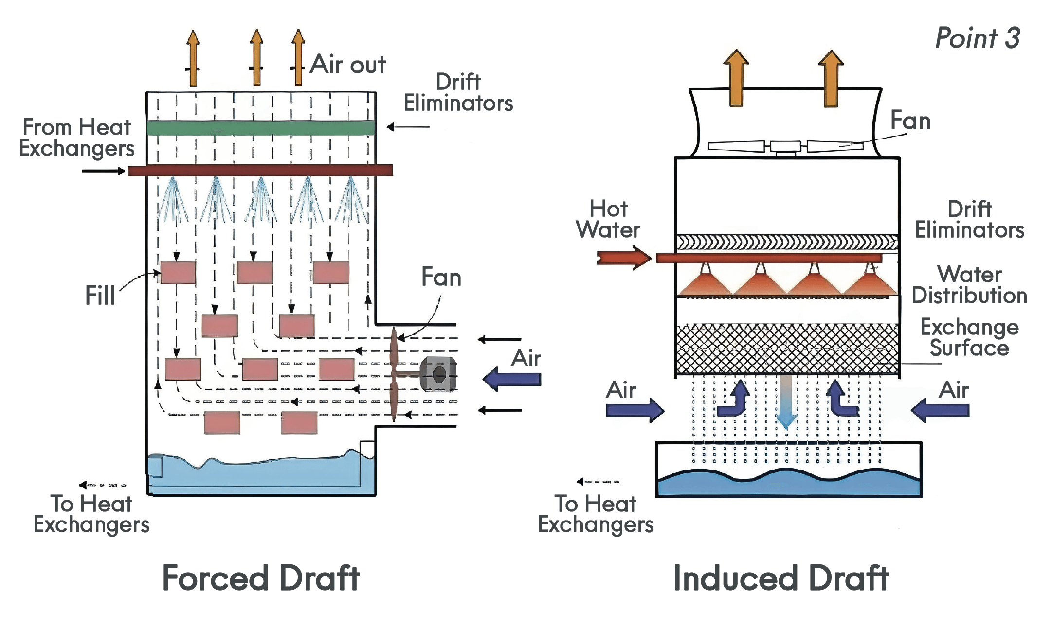
3. Mechanical Draft Cooling Towers
Although these units occupy a smaller footprint and lower building cost, they are less energy efficient – requiring additional power for the constantly running fan. (Point 3)
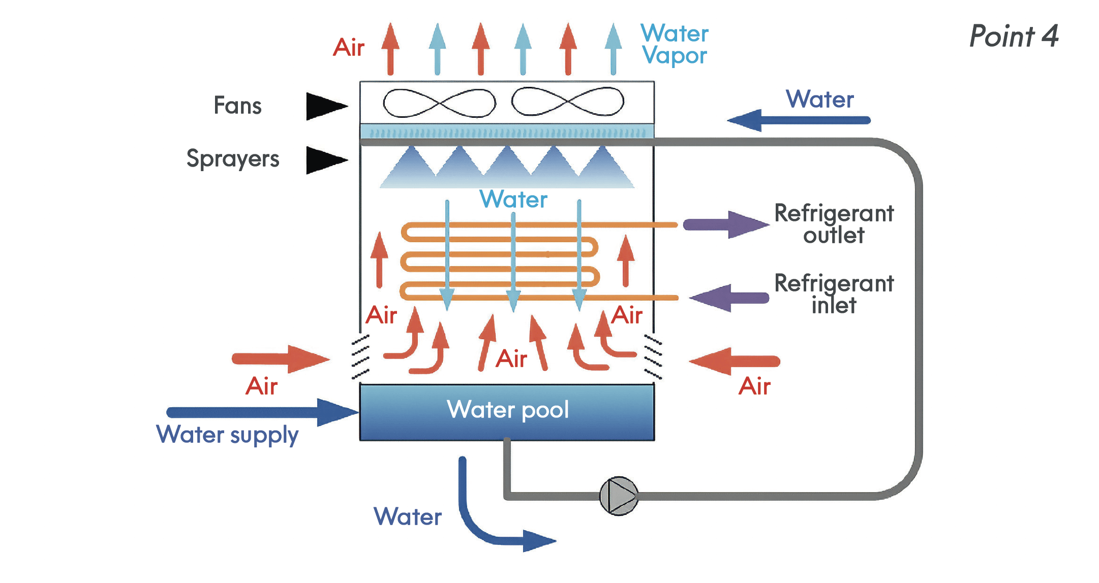
4. Evaporative Condensers
Evaporative condensers combine the principles of water cooling and air cooling. They use a fan to draw air through the condenser and over a water-sprayed coil. As the water evaporates, it absorbs heat from the refrigerant in the coil, effectively cooling it. This process benefits from the cooling effect of evaporation, making it more efficient than simple air cooling, especially in hot climates. Evaporative condensers are often used in places where water usage needs to be minimised since they consume less water than traditional water-cooled systems. They are suitable for various applications, including HVAC, refrigeration, and industrial processes. (Point 4)
5. Cold Well
This is an area that would benefit from better engineering and design. The size of the cold well is often dictated by the size and shape of the tower footprint that is available. No consideration is given to the predictive water chemistry and the requirement for water treatment.
The “thumb rule” for water treatment is that the reagent levels for corrosive waters are 5 – 10 times more than the treatment reserves for potentially scaling waters. It therefore seems logical to design cold well volumes for corrosive waters to be on the minimum whereas the cold well for potentially scaling waters can be greater. The larger volume would reduce the heating – cooling cycle and assist in preventing scale formation.
Cold Wells, apart from hyperbolic towers, are almost invariably quadrilateral tanks which will promote dead areas at the corners. Makeup inlet is generally opposite the circulating pump suctions which will help in preventing water flow short circuiting through the sump.
The cold well design would be better circular to eliminate dead corners and hopper bottomed to allow for on-line cleaning of deposited material.
Continuous make- up via a conventional ball valve is to be preferred to electronic level control to stabilise water chemistry.
Where high- and low-level probes are installed to control make-up and automatic bleed operation on cooling water conductivity there is a possibility of excessive water use. If high conductivity is detected coincidently with high water, then the bleed will stay open until low level is reached and the makeup is initiated.
Cooling Media Water
1. Principles of Evaporative cooling
See Appendix
2. Evaporative cooling water cycle
Water treatment control is based on the bulk water analysis. However, the water chemistry does vary throughout the cooling water cycle.
a. Heat Exchanger
b. Cooling Tower packing
c. Coldwell
Heat Exchanger
When a fluid flows over a stationary surface, e.g. the flat plate, the bed of a river, or the wall of a pipe, the fluid touching the surface is brought to rest by the shear stress at the wall. The region in which flow adjusts from zero velocity at the wall to a maximum in the mainstream of the flow is termed the boundary layer. The concept of boundary layers is of importance in all viscous fluid dynamics and in the theory of heat transfer.
Reynolds 1883
Reynolds demonstrated the transition from laminar flow to turbulent flow by injecting a jet of dye into the centre of a stream of water at various flow rates. From these experiments, he was able to derive the Reynolds number analogy for predicting laminar or turbulent flow.
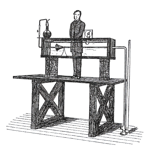
The boundary layer is important as this is where all the chemistry occurs rather than in the bulk water phase (see later predictive water chemistry).
Knudsen and Hays 1980
Invented an analyser for studying the potential build-up of deposit in the boundary layer by continuous online heat transfer which was much more accurate than looking for very small changes in water chemistry.
Cooling Tower packing
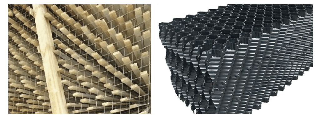
Legislation no longer allows lumber in cooling tower construction; hence tower packing is now plastic. The mechanics of air water contact for wooden slats and plastic fill are very different.
Splash Slats
The original cross flow towers were filled with triangular wooden slats installed with a flat surface towards the falling water. Since a sphere has the smallest surface to volume ratio, the slats were primarily functioning to break up the falling water droplets thus allowing for greater air contact. A secondary function was to slow down the passage of the water down the tower, again improving air water contact.
Current splash slats are far more efficient in breaking up the water droplets.
One of the properties we lost with the elimination of wood from cooling towers was the ability to adsorb certain biocides (particularly tri butyl tin oxide) for slow release enabling more effective biological control.
Vertical fluted fill
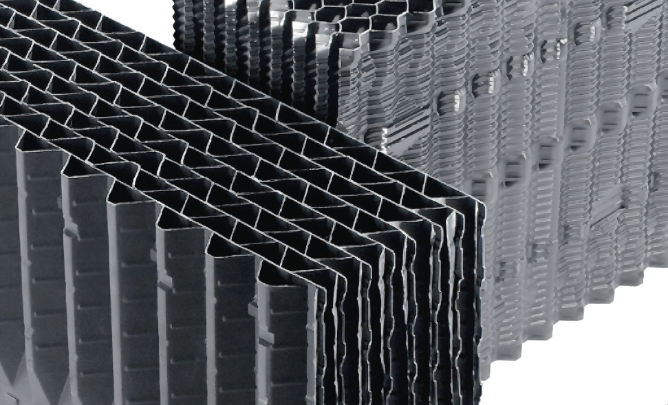
This type of packing is a narrow vertical channel designed to produce a film of water on the surface. This is an increase in surface area to volume compared with the water droplet but only one surface is in contact with the air flow. As the water progresses through the packing, it’s velocity must increase, further thinning the water film. At the bottom of the packing the thinnest film is in contact with the lowest humidity air flow. This is analogous with high pressure water tube boilers that depart from nucleate to film boiling which can lead to scale deposition.
Water chemistry
Evaporation and hence cycling takes place in the packing. An increase in dissolved solids, possible loss of carbon dioxide – increasing pH and temperature falling all enhance the possibility of scale formation.
Countering the “Henry Ford” Syndrome
Micro-management of many recirculating systems has demonstrated that the systems are not as stable as plant managers are led to believe. Necessary operational requirements such as swinging compressors on a chiller plant or changing cooling towers can have an impact on the water chemistry.
System 1
Changing duty and standby chiller generally requires the standby chiller to be started before the operational unit is taken off-line. This will result in a instantaneous increase in the circulating volume of the cooling system with a corresponding lowering of the water level in the sump. This will be compensated for with an increase in make-up. When the standby unit has stabilised, the on-duty can be shut down. The reduction in circulating volume can return to the sump, possibly causing an overflow.
Water Chemistry
The increase in make-up due to sump level reduction would cause a reduction in cycles of concentration and treatment levels would be reduced. Treatment dose should be controlled on purge rate, hence overflow of the system would not be registered so no treatment would be added.
To simply restrict make-up during this operation could be dangerous and open the risk of the system running dangerously low.
System 2
Cooling water is often used for other purposes than evaporative cooling. Where full or side stream filtration has been installed on a recirculating cooling system, cooling water is generally used for backwashing the filter. This is false economy as the system water will contain treatment and is more expensive than make-up water.
The backwash would not register as controlled purge so no addition of treatment would occur. Also, the replacement make-up would further reduce cycles of concentration and treatment reserves.
Tower controllers need to be smarter to interpret these (and other more complicated) situations.
The foregoing highlights the individuality of various recirculation cooling systems, but we also must consider the treatment requirements for the separate parts of the cooling system rather than “any colour as long as its black”.
Microbiological considerations
The three main areas of the cooling system have differing microbiological environments:
1. Cooling Tower and packing
a. Warmest part of the system.
b. Partially exposed to sunlight.
c. Water fully oxygenated.
d. High risk of water contamination from airborne particulate.
e. Ideal environment for aerobic bacteria and algal growth.
2. Sump
a. Coolest part of system.
b. Possible bacterial ingress from make-up.
c. Low flow – Poor circulation.
d. Possible deposition from particulate material.
e. Ideal environment for both aerobic and anaerobic bacterial growth.
f. Biofilm generation may also encourage fungal growth.
3. Heat Exchanger and plant equipment
a. Velocity through heat exchange units should be sufficient to keep bacteria planktonic.
b. Low flow and dead areas encourage biofilm formation.
c. Engineering materials metallic (Iron – copper – aluminium) possible interaction with oxidizing reagents.
Micro-biological control
Chlorination was the earlier preferred method of biological control in cooling systems but as the availability of liquified chlorine gas became restricted due to potential handling hazards, Sodium Hypochlorite was used as an alternative. Quite often shock dosed to the tower sump.
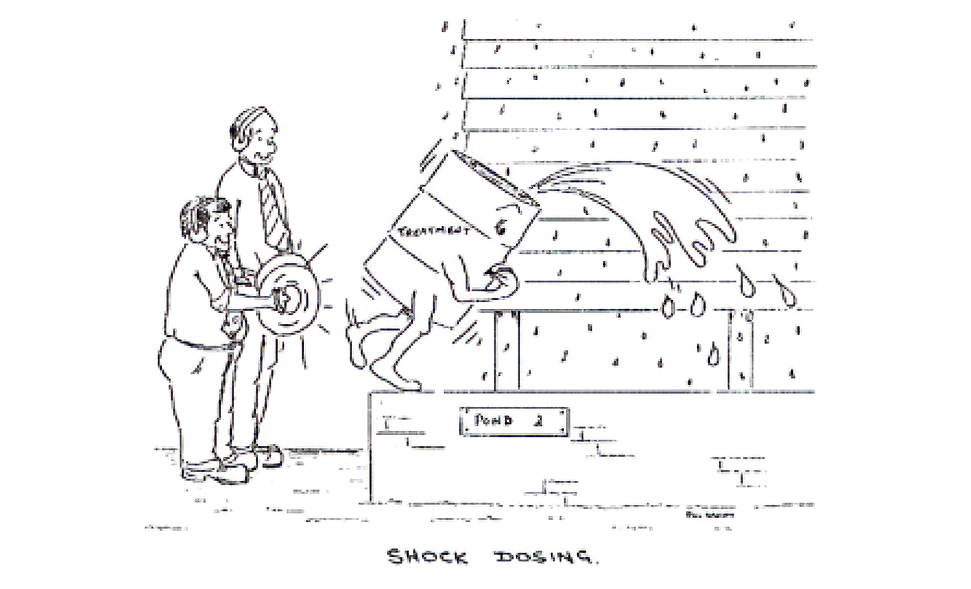
Shock dosing a cooling system was intended to hit the micro-organisms with a short exposure to an excess of biocide. However, it was not always possible to get the dose near to the pump suction for this to be effective and would be a last resort application today.
With the development of non-oxidising biocide application technology also developed:
1. Continuous application of oxidising biocide.
2. As above with intermittent addition of a supplementary nonoxidiser.
3. Dual non-oxidiser.
Continuous Application
Oxidising (Sodium Hypochlorite) biocides are possibly the most utilised regime. The biocide generally is dosed to the cooling tower sump and hopefully distributed and circulated throughout the system. These are the most cost-effective biocides, but they have some consequences that are detrimental to the cooling system.
1. Both hypochlorite and chlorine dioxide add undesirable chloride ion to the cooling water increasing the corrosion potential.
2. Hypochlorite is steam volatile reducing the effective concentration through the cooling tower.
3. Hypochlorite is also deactivated with ferrous metals.
Current legislation, particularly regarding Legionella control and maximizing water economy, a more precise application may be required paying attention to the requirements of the sections of the cooling system.
Maintaining a free chlorine reserve in the cooling water is almost certainly to be the general biocide regime using sodium hypochlorite solution. There are however several drawbacks.
1. The reagent is pH sensitive and will ionise to the less effective hypochlorite ion that will require a higher dose at a system water pH above 7.5.
2. Hypochlorite is steam volatile and we can expect as much as 30% loss over the cooling tower.
3. Ferrous metals will increase the degradation of hypochlorite.
1. Tower and packing
The tower packing has been identified as the more critical area for deposition – scaling and biological activity and required better attention. For maximum effect, the oxidising biocide should be fed to the return to the cooling tower rather than the tower sump. The biocide should be fed at 1 – 2 mg/≈ free chlorine for 20 minutes based on the flow rate. Also, the cooling tower fans should be switched off for this period. This will:
a. Reduce the volatility of the biocide.
b. Reduce the possibility of released bacteria and spores being transported from the cooling tower to contaminate the vicinity.
c. For multicell systems, this procedure should operate sequentially.
This can be repeated daily.
2. Exchanger
The heat exchanger required a less aggressive biocide, and an organic reagent is recommended. The application of the non-oxidising biocide should be made to the inlet to the exchanger (ideally to the circulating pump suction) at the kill concentration for one circulation of the system volume.
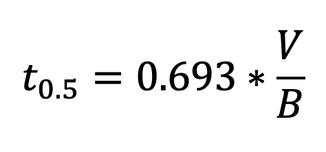
The biocide will deplete because of water lose (purge, drift etc) and should be dosed again as the concentration is halved every t0.5 hours), using the same dosing technique. The biocide requirement will be half the kill concentration.
3. Sump
The treatment for the exchanger will extend to the tower sump.
Fouling control
Scale control and fouling are bulk water phenomenon and the point of addition of the scale/corrosion/fouling control reagent is less critical but should be in an area to ensure rapid dispersion.
Dual non-oxidising biocide addition
The primary nonoxidising biocide should be dosed as above – at the kill dose for one turnover of the cooling system volume. Repeat dose can be as recommended above to maintain a constant reserve of biocide or as determined by the biological activity in the system.
The complementary non-oxidising biocide should preferably be added in the same manner at 2-to-4-week intervals. Shock dosing to the tower sump must ensure rapid mixing.
Postscript
This discussion has been aimed primarily on the understanding of the application of water as a cooling medium and the implications of the development of more efficient heat transfer. In many respects it is a nostalgic view of water treatment application – but in stating that, there is no implication that things were easier or better.
Chemicals for water treatment applications have developed at a much faster rate than heat exchange technology and have deliberately not been addressed in this discussion, (probably resulting in a much longer, in depth review).
With the rapid development of Artificial Intelligence accompanied by the increasing need for large data centres, water could easily become a scarcity. It is often said (correctly) that
“All water treatment reagents end up down the drain.”
So, we should look to the overall situation when considering a risk assessment of the cooling requirement. It is the fervent hope that this paper will promote review of current practices and encourage innovation and solving opportunities, rather than following excepted solutions.
APPENDIX
1. Principles of Evaporative cooling
When warm, dry and unsaturated air is pulled through a water-saturated medium – water evaporates from the medium to vapour in the air. The evaporation energy comes from the water which is cooled down.
Thermal conductivity of water 4.16 kJ kg¯¹ °c¯¹
Heat of Evaporation of water 2256 kJ kg¯¹
For a 1% water evaporation, the bulk water temperature will fall 2256/99*4.16 = 5.47°c.
(For practical use a 1% evaporation for every 7 °c is used).
The remaining cooled water will increase in dissolved solids because of the loss of water vapour.
James W McCoy 1974
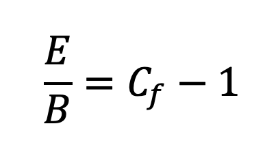
derived a model of evaporative cooling as a simple differential equation
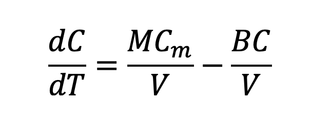
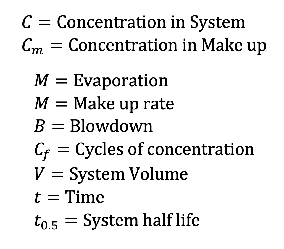
Where:
Concentration equation on Integration
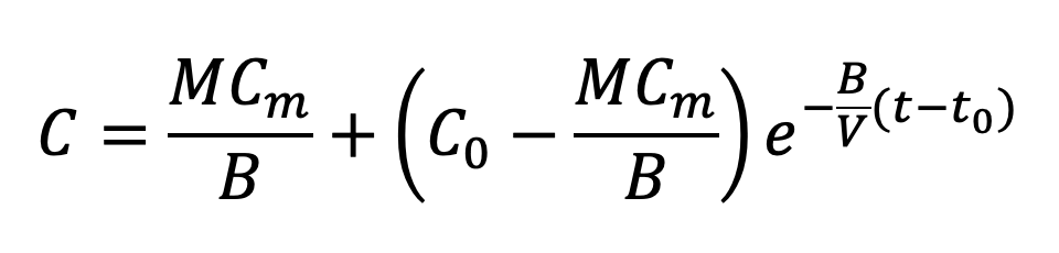
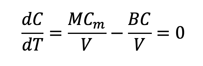
This algorithm can be used to accurately predict the cooling water analysis at any time, providing that all the variables have been determined.
There are several derivations from this model that are used in the control of cooling water chemistry.
Depletion
For shock treatment of systems, the concentration of an additive in the make-up will be zero. Therefore, the equation will reduce to:
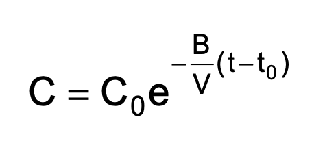
This equation can be used to determine the operating parameters of a cooling system if a tracer is introduced into the cooling water and concentration of the tracer is plotted against time.
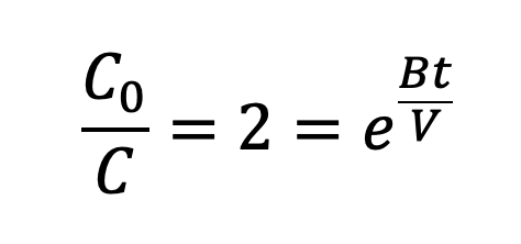
This derivation is most useful for calculating initial biocide dose to compensate for blowdown losses to ensure maintaining correct kill concentration of the recommended kill time.
For the case for calculating the depletion time to 50% of initial concentration the equation is:
Steady state water chemistry

Usually used